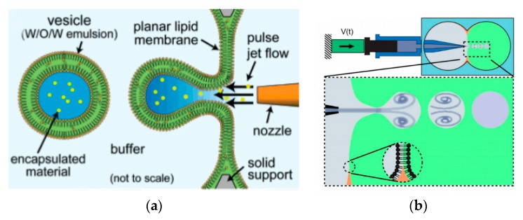
Figure 7.
(a) The illustration above shows the method used by Funakoshi et al. to produce giant vesicles. Reprinted with permission from reference [64]. Copyright 2007 American Chemical Society (b) The piezoelectric driven syringe that made up the microfluidic jetting device that was used to generate the giant liposome vesicles. The schematic of the close-up shows the process of the vesicle formation and highlights the interaction between the vortex ring structure that surrounds the vortex ring structure at the nozzle and the planar lipid bilayer. Reproduced from reference [97]. Copyright 2008 National Academy of Sciences (c) The giant vesicles were formed using microfluidic jetting using a piezoelectric inkjet. This method was also used to form GUVs containing oil insoluble lipids by incorporating SUV into the planar bilayer followed by microfluidic jetting. The content of the SUVs can be controlled in order to form GUVs with asymmetric lipid composition. Reproduced from reference [100]. (d) The encapsulation of the SUVs containing the vSNARE family proteins within a GUVs carrying the tSNARE protein. The mixing of the membranes leads to the incorporation of the SNARE protein from the SUV to the GUV. This closely mimics the movement of a transfer vesicles during exocytosis. Reproduced from reference [100].

