
Fig.3.
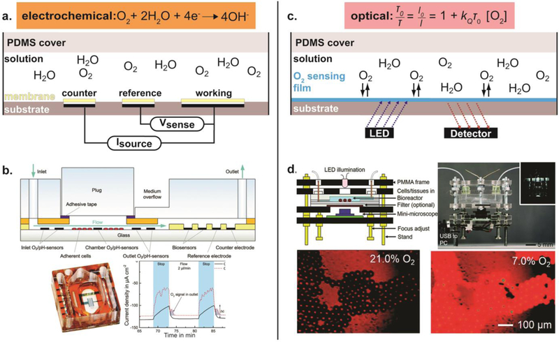
Measuring oxygen in microdevices. (a) Schematic of non-Clark type amperometric oxygen sensing. An optional membrane or coating can be applied over the electrodes to limit fouling or cell-electrode interactions. An oxygen-selective membrane can also be integrated to achieve a Clark-type system, i.e. using only an anode and cathode. (b) An example of amperometric oxygen sensing. (Top) Schematic of the fabricated microfluidic device. (Bottom, left) Fabricated microfluidic device with integrated electrochemical O2 sensors. (Bottom, right) Amperometric continuous oxygen measurement. Reproduced from Ref. 123 with permission from The Royal Society of Chemistry, copyright 2014. (c) Schematic of optical oxygen sensing. (d) An example of optical oxygen sensing. (Top, left) Schematic of the fabricated microfluidic device. (Top, right) Fabricated microfluidic device with integrated optical O2 sensors. (Bottom) Fluorescent images of the microbeads doped with two dyes, oxygen sensitive ruthenium dye and oxygen-irresponsive Nile blue, to 21% and 7% oxygen concentrations. Reproduced from Ref. 243 with permission from The Royal Society of Chemistry, copyright 2015.