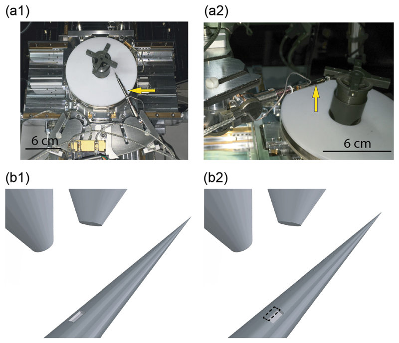
Fig. 6.
(a) Photographs of the micromanipulation system. The yellow arrow in panel (a1) highlights the xyz-ϕ motor, while the one in panel (a2) high-lights the tapered fiber and its holder. (b) Schematic representation of the ring fabrication process. After the realization of a first rectangular pattern (panel (b1)), the fiber is rotated around its axis by an angle of 20° and another rectangular pattern is partially overlap over the previous one (panel (b2)). (For interpretation of the references to color in this figure legend, the reader is referred to the web version of this article.)

