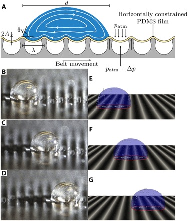
Fig. 1. Droplet transport on transverse wave surface topographies.

(A) Schematic of the experimental setup of the transverse wave device. Here, A is the wave amplitude, λ is the wavelength, θY is the contact angle, d is the typical droplet size, patm is the atmospheric pressure, and Δp is the pressure difference created by a vacuum pump to transform the flat PDMS film into a wave-like surface structure with a wavelength that is dictated by the ridge spacing of the belt. The streamlines inside the droplet are a schematic to illustrate the internal droplet flow in the center-of-mass frame following the droplet. (B to D) Glycerol droplet containing tracer particles transported by the traveling wave device (see movie S1). Here, A = 4 ± 1 μm, λ = 500 μm, and θY = 100 ± 2°. In fig. S1, the frames of the movie are superposed to generate path lines, demonstrating the treadmill-like internal flow pattern consistent with Fig. 1A. (E to G) Computational fluid dynamics (CFD) simulations of the glycerol droplet on a transversely deforming surface boundary for the same traveling wave characteristics (shape, wave amplitude, wave speed, and wavelength), droplet properties, and Young angle as in the experiments (see Materials and Methods and movie S2). The small arrows inside the droplet indicate the local fluid velocity in the center-of-mass reference frame.
