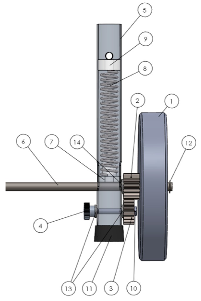
Figure 2.
Details of the self-locking mechanism (Approach 1). 1—unidirectional wheels; 2—upper gear wheel; 3—the bottom gear wheel; 4—hand-operated nut; 5—walker’s front legs; 6—calibrated steel solid shaft (axis); 7—lock-guide; 8—helical compression springs; 9—stopper fixed inside the leg; 10—semi-screw; 11—rubber feet; 12, 13 & 14—(flat) washers.

