
Fig. 1.
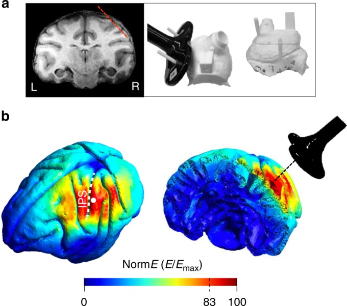
Brain targeting and model of the spatial spread. a Anatomical magnetic resonance image (left) and 3D models of the monkey’s skull (right) indicating respectively, the trajectory of the electrode during recordings (red, dashed line) and the coil positioning method. The right panel shows a top view (left) and a lateral view (right) of a 3D model. During the experiments, a 25 mm figure-of-eight TMS coil (black) was rigidly anchored to the monkey’s skull to allow precise and reproducible coil positioning across recording sessions. Two guiding rods were attached to the monkey’s head implant based on MRI estimations of the cortical target coordinates. b TMS-induced electric field as modelled with simNIBS. Left: rotated model of the brain indicating the normalized electric field distribution (spatial spread) calculated for the D25 coil. The white dot indicates the center of stimulation (center of the coil). Right: Coronal section of the brain across PFG