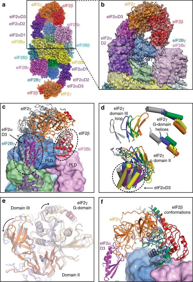
Fig. 3.
Contacts of eIF2 β and γ with the catalytic subunits of eIF2B. a eIF2B–eIF2(αP) complex model in spheres representation fitted in map A showing tilted conformation of eIF2γ, which is stabilised by its contact with eIF2Bγ and extended conformation of eIF2β contacting the interface area of the two γ and ε catalytic subunits of eIF2B. b Close-up view of the model fitting into the density of map A. c Modelled positions of eIF2 γ and β subunits after classification, showing extensive movements of these subunits around eIF2B ε and γ PLD domains. For clarity, only two eIF2 models are shown (corresponding to maps A—coloured and C—grey). d Modelled positions of eIF2γ subunit and eIF2α-D3 in all three maps (map 1—orange for eIF2γ and purple for eIF2α-D3, map A—blue, map B—green, map C—grey, map D—yellow). For clarity, only few elements in each of the eIF2γ domains are shown. e Superposition of domain II of eIF2γ in map A (coloured light blue) with that in map 1 (eIF2γ coloured orange) shows the rearrangement of three eIF2γ domains when it is in the tilted conformation. f Conformation of eIF2β fitted in map D (red) is different from the conformations found in three other maps (A - blue, B - green and C - grey). eIF2 γ and α shown are from map D

