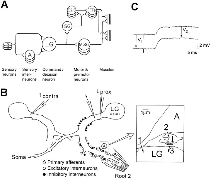
Fig. 1.
Anatomical background and methods.A, Schematic diagram of the neural circuit for LG escape reactions. A, Interneuron A. LG, Lateral giant; SG, segmental giant; MoGs, motor giants; I2,3, intersegmental neurons 2 and 3; FFs, fast flexor motoneurons. B, Diagram of LG dendrites as seen in transverse section (dorsal up), showing the location of anatomically classified synaptic inputs to LG (Lee and Krasne, 1993) and the sites of microelectrode placement. The bilateral LG neurons are electrically coupled by commissural synapses near the midline of the ganglion; part of the contralateral LG neuron is drawn. Iprox, Current injected into the initial segment of the axon, proximal to the recording electrode; Icontra, current injected into the contralateral LG. Inset (right) is a diagram based on electron micrographs (Lee and Krasne, 1993) of a region of contact between interneuron A and an LG dendrite.1, A presumed excitatory synapse between interneuron A and LG. 2, Synapse between interneuron A and a GABAergic inhibitory neuron (I). 3, Synapse between inhibitory neuron and LG dendrite. C, Definition of voltage changes used to compute percentage reduction ofVprox and Vcontra in LG during a synaptic potential. Shown is a depolarizing recurrent inhibitory IPSP produced by stimulating MG while LG is at normal resting potential (top) and during hyperpolarization of LG with injected current (bottom).

