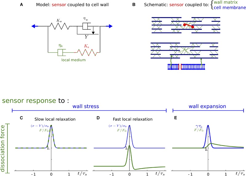
FIGURE 4.

Sensor associated with a minor load-bearing structure. (A) The sensor and the structure with which it is associated are schematically represented by a spring in parallel to the cell wall. The elastic modulus Ks accounts for the sensor and the structure in which it is inserted. The viscosity ηs is a property of the structure, only. (B) Schematic of the cell wall showing that the minor load-bearing structure may be a matrix component or the plasma membrane. (C–E) Response of the sensor to a mechanical signal: stress (C,D) or strain/expansion (E). Mechanical signal (input, blue) and dissociation force (output, green) are plotted as a function of time. Stress is normalized using the yield threshold, Y; and an arbitrary stress level, σ0; expansion rate is normalized by 1/τ0 = σ0/(Kwτs); dissociation force is normalized by F0 = Ks/Kwσ0; time is normalized with local relaxation time τs. (C,D) Correspond to the ratios τs/τw = 2 and τs/τw = 1 of local to cell wall relaxation time, respectively.
