
Figure 1.
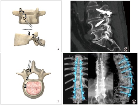
Medio‐lateral superior trajectory (MLST) for cortical bone trajectory screws. (A) Model showing the starting point for the MLST technique (Point 1). Points 2 and 3 demonstrate the trajectories that the surgeon can use during lateral or anteroposterior radiography, respectively. (B) Model showing the axial trajectory for an MLST screw (arrow). The screw follows a medial to lateral path, thus avoiding lateral dissection of the paraspinal musculature. (C) Lateral radiograph showing the trajectory of an MLST screw in L 3, starting at the pars with the screw angled towards the lateral aspect of the endplate. Note the L 4 pedicle screw is angled in a superior‐inferior direction, the opposite of the MLST screw. Image adapted with permission from Mobbs et al.30. (D) Three‐dimensional CT demonstrating CBT/MLST screw insertion.