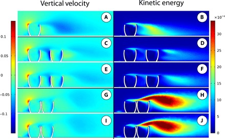
Fig. 3. CFD results.

Results of CFD simulations in vertical cross-sections showing vertical velocity (left column) and kinetic energy (right column). All models oriented parallel to flow, at moderate burial depth, and simulations were performed using an inlet velocity of 0.2 m/s. (A and B) Single-model simulation. (C to F) Spaced multiple-model results, where (C) and (D) show left column of individuals and (E) and (F) show right column of individuals with respect to flow. (G to J) Clumped multiple-model results, where (G) and (H) show left column of individuals and (I) and (J) show right column of individuals with respect to flow.
