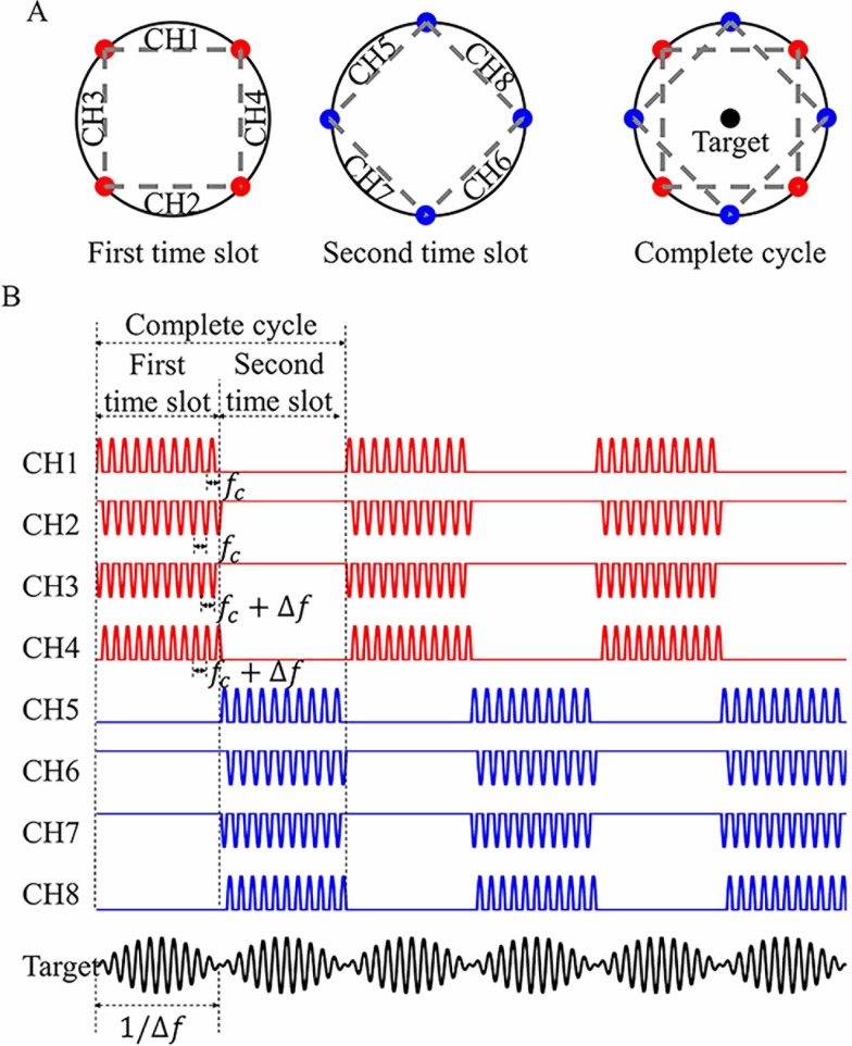
Fig 1. Conceptual illustration of multiple (time-division, frequency and polarity) modulation synthesis (MMS).
(A) Arrangement of multiple electrodes acting in the first time slot (red), second time slot (blue). Target: the desired target region. (B) Output waveforms from various channels (CH1, CH2, …, CH8) and their superposition with the same amplitude (Target). CHs 1–8 are applied with positive and negative aspects of sine wave with different high carrier frequencies of fc and fc+Δf (fc = 2 kHz, Δf = 100 Hz), respectively. Each of the four channels reproduces low-frequency (Δf) envelope in their respective time slots. Please note that the length of kilohertz-frequency wave is shown disproportionally for better visibility.

