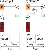
Figure 3.

Setups (top) and time tables (bottom) used for SAMBADENA. Setup 1: The pH2 reservoir was connected to the inlet of the reaction chamber (R). Valve V1 was opened for a period of t pH2 to initialize the chemical reaction. The SOT sequences were executed after an additional delay (t delay), resulting in a total hydrogenation time t hydr. After detection of the hyperpolarized signal, valve V2 was opened to clear the system. Setup 2: In addition to setup 1, a bypass was installed to equalize the pressure after t pH2, reducing the bubbling. V3 was opened after t pH2 for time duration t bypass.
