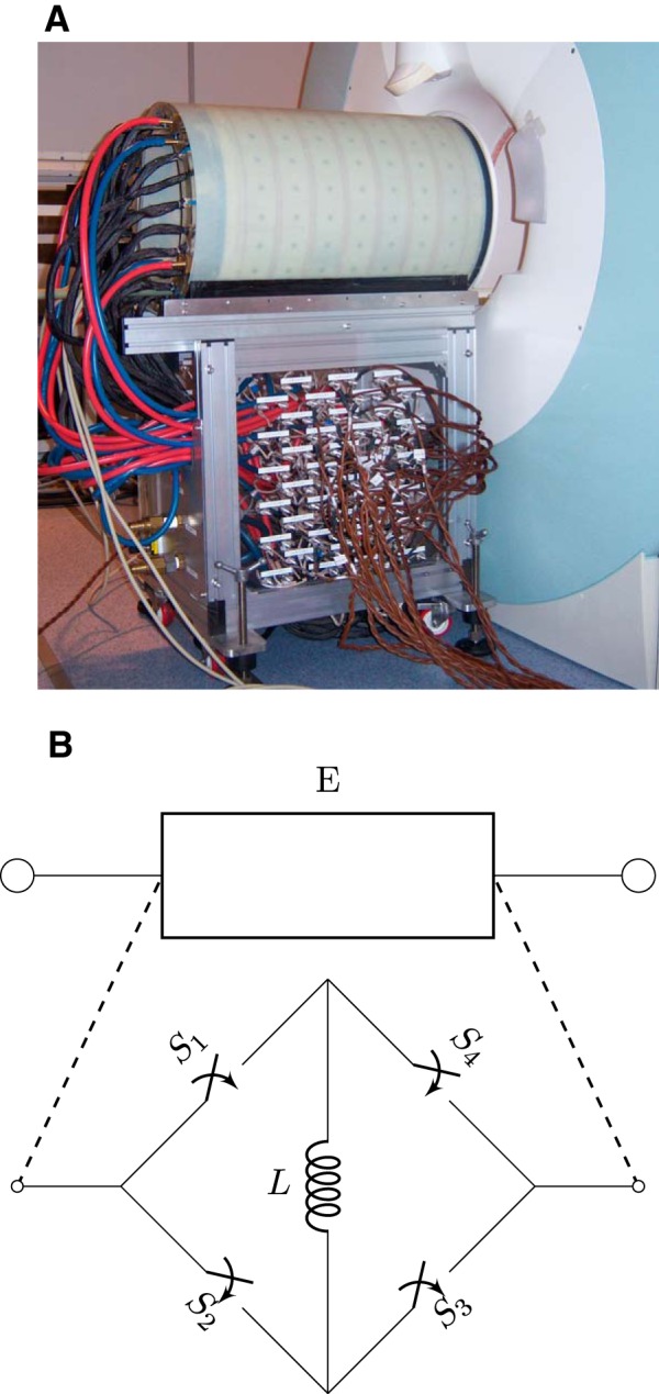
Figure 2.

Implementation of the matrix gradient coil shown at the backside of a Siemens Trio scanner (A). To conduct measurements, the coil is pushed into the isocenter of the scanner. The black connections feed current to the individual coil elements. The water cooling is supplied by the red and blue hoses. On the side of cart are connector boards with connections for every coil element. A schematic representation of a coil element E which consists of the coil windings L equipped with a bridge switch (B). This allows to route current through the element in both directions. One direction is achieved by having the switches S1 and S3 in on-state and S2 and S4 in off-state. The other direction is achieved the other way around. In addition, the bypass mode can be achieved by having control switches S1 and S4 in on-state and switches S2 and S3 in off-state, or the other way around.
