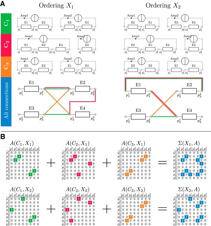
Figure 3.
(A) Illustration of how changing the ordering of coil elements within a cluster can affect the number of switches for a matrix gradient coil with 4 coil elements (E1, E2, E3, E4; each box represents a circuit as shown in Figure 2B), 2 amplifiers (Amp1, Amp2), and NF = 3 configurations (C1, C2, C3). (B) The initial ordering X1 and the updated ordering X2 are shown in the left and right columns, respectively. The first 3 rows show how the coil elements are assigned to and supplied by amplifiers to create the NF target fields. The fourth row summarizes all connections between coil elements for each setup. Terminals are labeled with the symbol p. Observe that in C1 the ordering of E1 and E2 changes in the first cluster, whereas in C2 the ordering of E1, E2, E4 changes to E2, E1, E4. Configuration C3 remains unchanged. As can be seen in the last row, X1 has only 1 connection between terminals which is used by 2 configurations, whereas X2 has 2 shared connections. While the ordering X1 requires 5 switches, the ordering X2 requires only 4 switches. Corresponding adjacency matrices of the undirected graph representing 2 configurations, X1 (top) and X2 (bottom). Each nonzero entry represents a connection between 2 terminals of the coil elements. Applying equation (2) to each of the 2 adjacency matrices (X1; A) and (X2; A) gives the final number of switches, which is 5 for X1 and 4 for X2. Similar strategies can be followed for the switches connecting the amplifiers to the coil element network (Figure 4).

