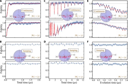
Fig. 4. Performance of adiabatic protocols along geodesics.

(A) Measured fidelity (blue dots) between the final state and the target adiabatic state as a function of the total time by using a continuous driving protocol with a constant gap Ω0 = 2π × 5 MHz. The inset indicates the control path where the instantaneous eigenstate ∣ψ1(λ)〉 of the Hamiltonian proceeds from ∣x〉 to the ∣ − x〉 via a geodesic half circle. The initial state ∣ψ1(0)〉 = ∣ Ψi〉 is prepared in the initial eigenstate ∣x〉 (top) or ∣y〉 (bottom), the equal superposition of initial eigenstates. The target state is defined as the state driven by an ideal, infinitely slow adiabatic evolution. The red lines show the numerical simulation that has taken experimental noise sources into consideration (see Materials and Methods). The horizontal gray lines indicate the level of unit fidelity. (B) Same as (A) but for a jumping protocol where the π pulses have the same amplitude as the continuous protocol but are applied at the path points λj without time delay. The crosses in the inset illustrate the path points for N = 5 pulses. (C and D) Same as (A) and (B), respectively, but for a longer path containing six half circles by using three times of back-forward motion. (E and F) Fidelity during the evolution for a total time T = 3 μs using the protocols in (C) and (D).
