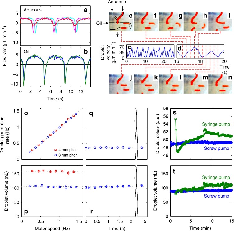
Fig. 2.
Anti-phase pulsatile flow and its use in droplet generation. a, b Flow rate over a three-pulse period for three aqueous lines (a): perfusate (probe push), dialysate (probe pull) and reagent, and the two oil lines (b). c Downstream velocity of droplets generated by the pulsatile flows (a, b) at a T-junction. d The linear droplet velocity for a single pumping period composed of one aqueous and oil pulse. The dashed lines correlate the velocity data to droplet generation at the T-junction (e–n) showing the controlled generation of a single droplet in the single pumping period. Scale bar in (e), 1 mm. o The droplet generation rate increases linearly with motor speed (and hence flow rate) for both 3 mm (blue circles) and 4 mm (red squares) screw thread pitches. The points fit on a straight line of unity gradient indicating that one droplet is produced in one turn of the pump. p Droplet volume is constant with respect to motor speed (and hence total flow rate) with different values for different pitch sizes. Error bars show the standard deviation in droplet size. q, r Droplet generation rate and volume remain constant when run at constant conditions (0.37 Hz, 3 mm pitch) over several hours. Error bars in (r) show the standard deviation in droplet size. s, t Comparison of the composition and size of droplets produced immediately after start-up using the screw-driven pump with 3 mm pitch (blue circles) and syringe pumps (green squares). The screw-driven pump instantaneously produces droplets of uniform composition (s) and volume (t), while the syringe pump shows significant drift over time

