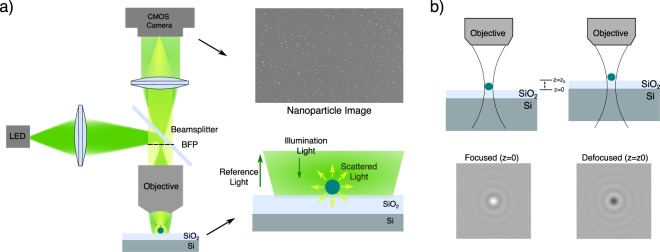
Figure 1.
Experimental configuration of the interferometric imaging system. (a) Optical Setup. An LED is focused on near back focal plane of the microscope objective to have slightly converging illumination on sample substrate (See Methods). Scattered light from nanoparticles and the reflected reference light is collected and imaged to a camera plane. A layered Si/SiO2 with 100 nm oxide thickness is used as a sample substrate. (b) Defocusing Response. Upon defocusing, the path length between the reference and scattered light changes, hence constructive and destructive interference can be observed.

