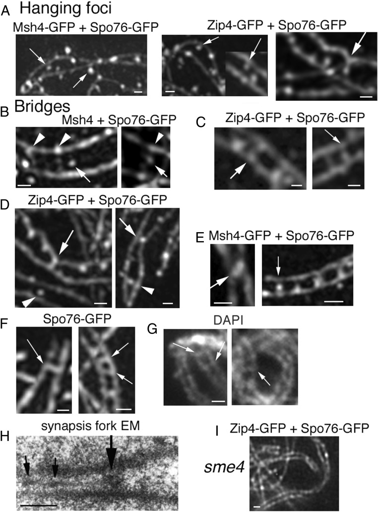
Fig. 2.
Interaxis bridges. (A–E) 3D-SIM pictures with costaining of Spo76-GFP (axes) and Zip4-GFP or Msh4-GFP. (A) First step: Msh4 foci (Left; arrows) and Zip4 foci (Middle; arrows) partially “detach” from their coaligned axes. (A, Right) Axis indentation with attached focus located in-between axes (arrow). (B) Examples of early bridges when axes are at 400-nm distance with Msh4 foci located in-between axes (arrows) sometimes (Right) linked by bridge-like structures (arrowheads) or nearby such structures (Left). (C) At the 200-nm coalignment stage, Zip4 foci are located either at matching sites (arrow, Left) or on bridges (arrow, Right). (D) Two examples of single Zip4-GFP foci located in-between axis. At 100-nm distance (arrows), axes are “constricted” by foci that are either fusing (Left) or are single (Right). At 200-nm distance, foci are in the middle between two straight axes (arrowheads). (E, Left) Two fusing Msh4 foci (arrow) with close axes. (E, Right) Row of four bridges with single Zip4 foci (arrow). (F) Spo76-GFP is visible on bridges (arrows) when axes are at 200-nm (Left) and almost 100-nm (Right) distance (3D-SIM). (G) Examples of DAPI bridges visible when homolog axes are at 200-nm (arrows) distance (classical fluorescent microscope). (H) EM section of a pairing fork with a bridge-like structure (large arrow). Note that SC initiates at one side of this structure and exhibits two small recombination nodules (small arrows). (I) In the absence of Sme4, homologs coalign but Zip4 foci remain on axes. (Scale bars: 200 nm.)

