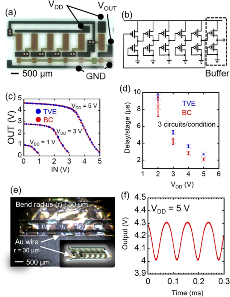
Figure 5.
Organic ring oscillator with a TripOMe modification layer. (a) Optical micrograph of a ring oscillator. (b) Circuit diagram. (c) Transfer curves of diode-load inverters. Blue curves represent the performance of an inverter with TVE-TripOMe. Red curves depict the performance of an inverter with BC-TripOMe. (d) Signal delay/stage of ring oscillators with a TVE-TripOMe (Blue cross) and BC-TripOMe (Red cross). (e) Photograph of a ring oscillator rolled onto a Au wire, 30 µm in radius. (f) Output wave of a ring oscillator after rolling up on a 30-µm-radius Au wire.

