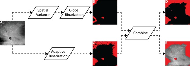
Figure 5.
Workflow for automatic detection of low-OCT-signal artifacts. (A) Input en face OCT image. (B) Spatial variance mask to detect segmentation errors, formed by computing the spatial variance of the OCT image (9 pixel × 9 pixel kernel), and then binarizing the resulting variance image using an empirical threshold determined from the qualitative observations of a single grader. Additional morphological steps (closing and erosion) are used to remove spurious regions. (C) Low OCT signal mask, formed by an adaptive binarization of the input OCT image. In particular, a dynamic threshold (3 pixel × 3 pixel kernel) is computed relative to the mean intensity of the input en face OCT image. (D) Output artifact mask, formed by combing the masks of panels (B,C); again, morphological processing (erosion) is used to remove spurious regions. (E) Overlay of the output artifact mask on the input en face OCT image.

