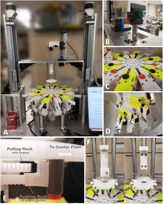
FIGURE 5.
The 2nd generation of micro braiding machine. (A) Full view photograph of the micro braiding machine. Behind the LCD touch screen control, which is partially visible at the bottom right corner, the newly developed electronic control box is located (see Figure 4 for details). (B) A small micromanipulator is used to adjust the center position of the core holder base. Adjustments center the core depending on different types of core holders used for different core materials and shapes. (C) Photo of inner and outer braiding plates with two different colored movers in orange and black. Outer modular plates have two different colors to easily distinguish the two groups used for a traditional simple braid: the clockwise and counterclockwise groups. Red lit tiny white blocks under the outer modular plates are the boxes having object detecting sensors with red LED indicating the status of object detection. (D) Photo of the view from under the braid plate. The rectangular black boxes connected with wire bundles seen are the object detecting sensors. (The sensor is inside the small box glowing red light under the front outer plate. Left photo: the red light means that an object (mover) is detected.) The small white rectangular blocks under the inner circular plate are the magnet holders used for centrifugal motions to magnetically grab movers when movers are in the inner central shelters. A plastic tube covers the center motor, wires, and supporting mechanical parts to prevent wires tangling or trapping in moving elements. (E) Image of two racks with different tips (magnet and plastic grabber) and a mover from under one of the outer plates, to show the mover driving mechanism as conceptually shown in Figure 1A. (F) Photos of detachable core holder system. The left shows the 1 ml syringe holder and the right shows the core holder base with four magnets without any type of core holder.

