Fig. 2.
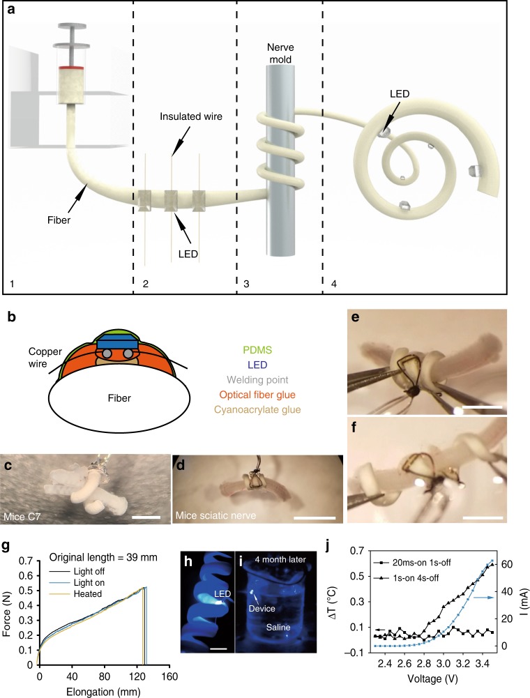
Fabrication and performance of the multisite optogenetic stimulation device (MOSD). a Flow chart for MOSD fabrication. (1) Production of a polyurethane fiber; (2) attachment of mini-LEDs to the fiber; (3) shaping of the fiber into a spiral shape; (4) final device. b Schematic diagram of device encapsulation. c, d Images of the MOSD wrapped around nerves with different diameters. c Mouse C7 nerve. d Mouse sciatic nerve. e An image of the MOSD at its original length fixed onto the mouse sciatic nerve. f An image of the elongated MOSD in e. g Mechanical properties of the polyurethane fiber under light or heat. LED was turned on at 2.5 V, 20.7 µA (0.0012 mW). The device was kept at 50 °C in the heated condition (green line). The original length of the MOSD is 39 mm. h The MOSD with mini-LEDs turned on in saline. i The MOSD with mini-LEDs turned on after 4 months continuously submerged in saline. j I–V curve as well as temperature changes at different input voltages for the mini-LED. Voltage applied to the mini-LED varied from 2.3 to 3.5 V (0.00003 mW–33.1 mW). The stimulation patterns for applied voltages are 20 msec-on/2 sec-off and 1 sec-on/4 sec-off. Scale bars are 400 µm (c), 2 mm (d), and 1 mm (e, f)

