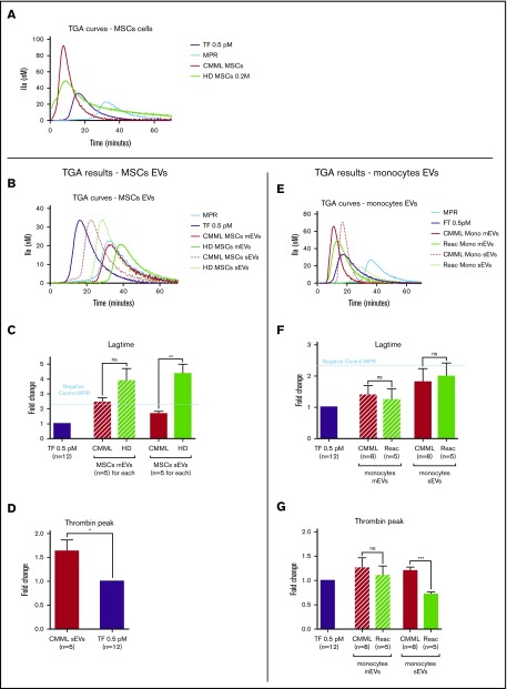
Figure 2.
The procoagulant impact of CMML MSCs and monocytes is conveyed by sEVs. Lag times and thrombin peak are expressed as fold changes of values obtained with positive control (TF 0.5 pM). The negative control used was MPR 0.5. Any thrombin generated after corresponded to contact-phase activation. CMML EVs are represented in red, HD EVs in green, and TF 0.5 pM in purple. Continuous curves represent mEVs, and dotted curves represent sEVs. *P ≤ .05, **P ≤ .005, ***P ≤ .0005. (A) TGA curves of 0.2 million CMML MSCs and HD MSCs compared with 0.5 pM TF. (B) TGA curves of CMML and HD MSC mEVs and sEVs. (C) Coagulation lag time for CMML and HD MSC EVs. (D) Peak of thrombin generated by CMML MSC sEVs. (E) TGA curves of CMML and reactional monocyte mEVs and sEVs. (F) Coagulation lag time for CMML and reactional monocyte EVs. (G) Peak of thrombin generated by CMML and reactional monocyte EVs. Mono, monocytes; ns, not significant.

