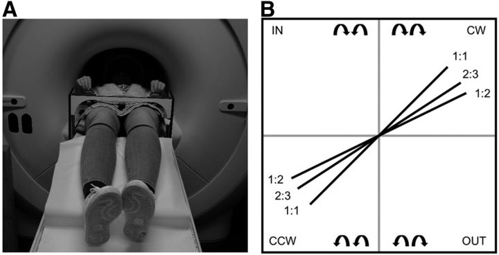
Figure 2.
A, Experimental setup in the (dummy or actual) scanner. Participants lay in a supine position on the table of the MRI or dummy scanner with the task device positioned over the participants' upper legs. B, All possible bimanual directional combinations (n = 2) and frequency ratios (n = 3). Schematic representation of the target lines presented into two possible coordination directions (CW and CCW) and three frequency ratios (1:1, 2:3, and 1:2).

