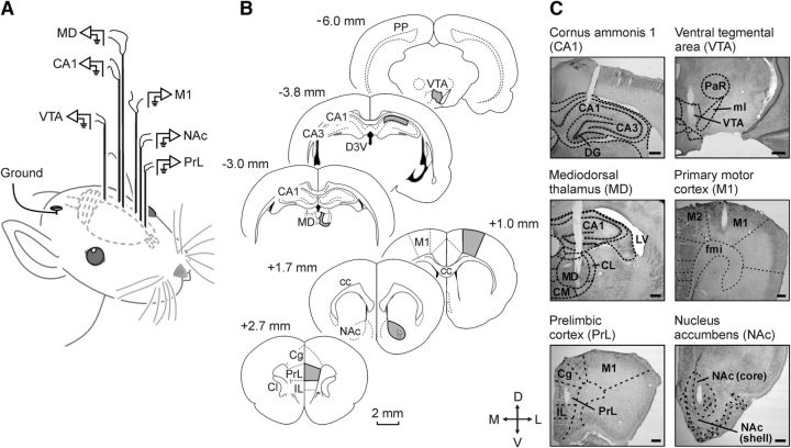
Figure 1.
Experimental design for brain stimulation and LFP recordings. A, Schematic representation of the location of stimulating and recording electrodes. B, Diagrams of brain sagittal sections illustrating in gray the implanted cortical and subcortical areas. Coordinates with respect to bregma are indicated. C, Representative photomicrographs illustrating the location of implanted electrodes. Cg, Cingulate cortex; IL, infralimbic cortex; CC, corpus callosum; Cl, claustrum; CL, centrolateral thalamic nucleus; CM, central medial thalamic nucleus; D3V, dorsal third ventricle; DG, dentate gyrus; fmi, forceps minor of the corpus callosum; LV, lateral ventricle; ml, medial lemniscus; PaR, pararubral nucleus; PP, perforant pathway; D, dorsal; L, lateral; M, medial; V, ventral.

