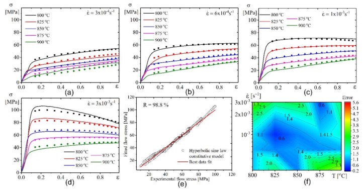
Figure 11.
Comparative plots for the experimental results (lines) and fitted values by hyperbolic sine law model (symbols) at (a) 4 × 10⁻⁴ s−1, (b) 6 × 10⁻⁴ s−1, (c) 1 × 10⁻³ s−1 , and (d) 3× 10⁻³ s−1 ; (e) the correlation between experimental and fitted flow stress; (f) the error between experimental and tested flow stress.

