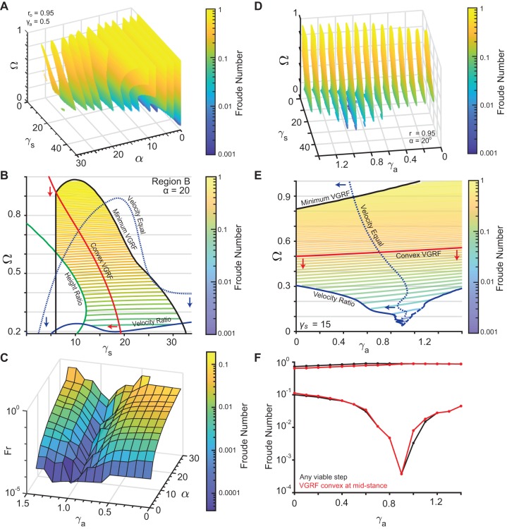
Fig. 3.
Non-dimensional analysis of the ARSLIP model. (A) A sequence of 2D slices each corresponding to one value of α. The colored area is allowed under the constraints described in Fig. 1D. Colors represents the Froude number. The vertical mid-stance height r˳ is fixed at 0.95 and γa set to 0.5. (B) 2D contour plot of the α = 20 degrees slice for r˳ = 0.95 and γa = 0.5 as in A. Similar to Fig. 2B, red is the boundary of the minimum VGRF criterion, blue the velocity criterion and green the height criterion. The dotted line represents the region where the velocity at the end of single-support equals the mid-stance velocity. Red arrows indicate the region where the vertical ground reaction force is minimum, while blue arrows point to the region where the velocity at mid-stance is less than the velocity at the end of single-support. Contour lines represent the Froude number of the allowed gaits. (C) This depicts the minimum Froude numbers for the gaits that meet the Vr, Hr and Gr constraints, plotted against α and γa with a fixed r˳ of 0.95 and minimizing over the other parameters. As γa increases, the slowest steps that can be modeled decrease. (D) 2D color-contour plots with color representing the Froude number with Ω, γa and γs varying, r˳ set to 0.95, and α set to 20°. Each slice corresponds to different values of the angular spring. (E) 2D slice from D, with γs = 15. Same color code as B. The dashed line along the velocity ratio criterion indicates that the boundary is linearly interpolated since the simulation could not resolve the boundary continuously. (F) The range of Froude numbers possible when α = 20 and r˳ = 0.95 for different values of γa with γs and Ω free to vary. The black curve represents any steps that meet Vr, Hr and Gr, while the red curve is for the steps that additionally meet the convex VGRF criterion.

