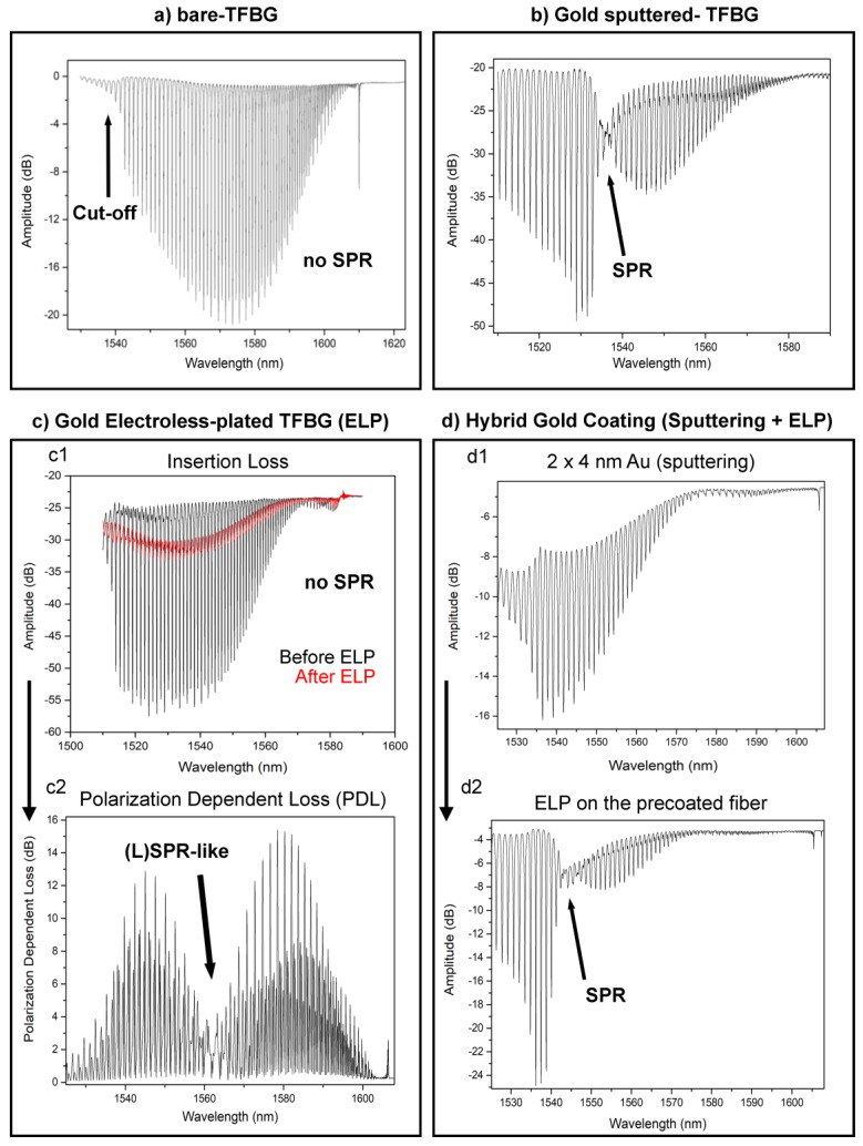
Figure 3.
(a) Bare-TFBG amplitude spectrum monitored in PBS with the sensing part located at the cut-off area. (b) P-polarized spectrum of a sputter-coated TFBG with the most sensitive modes located at lower neighbor wavelengths of the SPR attenuation. (c1) Transmitted amplitude spectrum before and after ELP process. (c2) The same plating leads to a pronounced change in the PDL spectrum. (d1) The deposition of a ~4 nm-thick gold layer by sputtering does not lead to SPR attenuation. (d2) While the ELP is performed on that layer, the reaction can be stopped at the optimum point to reach SPR excitation using classical insertion loss interrogation.

