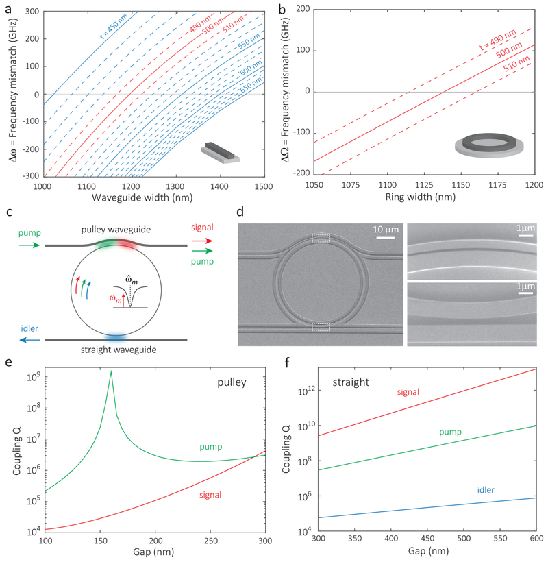
FIG. 2: Design and Simulation.
a, b, Simulated frequency mismatch (Δω = ωp − (ωs + ωi)/2) for phase-matched pump, signal, and idler modes (2mp = ms + mi), as a function of ring waveguide width (x-axis) and thickness t (different displayed curves). Calculations are based on (a) a model in which straight waveguide dispersion (no bending effect) is used, and (b) a full model in which the ring dispersion is used. The signal photon is at 668 nm, the idler photon is in the 1550 nm band, and the pump is in the 930 nm band. c, Waveguide-resonator coupling scheme, d, Scanning-electron-microscope images of a fabricated device with pulley waveguide on top, for injecting the 930 nm band pump and extracting the 660 nm band signal, and straight waveguide on bottom, for extracting the 1550 nm band idler, e, f Simulation of the coupling Qs of the pulley waveguide and straight waveguide, for the pump/signal and pump/signal/idler, respectively (the pulley waveguide does not support a mode at the idler wavelength).

