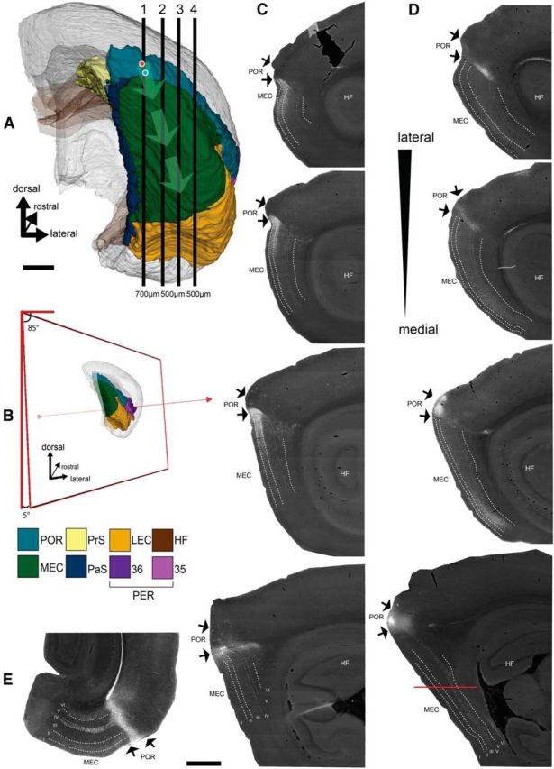
Figure 1.

Spatial organization of the projections from POR to MEC. A, Posterior view of the right hemisphere of the rat brain (Boccara et al., 2015; Kjonigsen et al., 2015) showing the position of POR and MEC among the other parahippocampal domains. Vertical numbered lines (1–4) indicate the approximate position of 4 representative sagittal sections presented in C, D. The location of two representative injection sites of the anterograde tracer BDA into dorsal and ventral POR are represented by red and blue circles, respectively. Light green arrows emerging from the two injection sites indicate the centers of the main terminal fields in ventral and dorsal MEC, respectively. B, Schematic representation of the selected orientation (5 degree tilt from the sagittal plane) of the in vitro slices based on the anatomical data (illustration prepared using the available slicing toolkit on http://software.incf.org/software/waxholm-space-atlas-of-the-sprague-dawley-rat-brain/waxholmspace-atlas-of-the-sprague-dawley-rat-brain-package/v2). C, Anterograde labeling in POR and dorsal MEC resulting from the ventral POR injection. D, Anterograde labeling in POR and ventral MEC resulting from the dorsal POR injection. There is major fiber labeling in the lamina dissecans (IV) in some of the sections. Because of the orientation of this pathway almost parallel to the plane of sectioning, this is much easier appreciated in horizontal sections taken from an animal with a comparable injection in dorsal POR, as illustrated in E. Sections are arranged from medial to lateral (A1–A4). The mediolateral level of the section that contains the injection is always medial to that showing the densest anterograde labeling in MEC. E, Horizontal section through the entorhinal cortex, taken at a dorsoventral level indicated in D, showing the prominent axonal labeling in the lamina dissecans of MEC. HF, Hippocampal formation; LII, layer II; LIII, layer III; LV, layer V; LVI, layer VI. Scale bars: A, C–E, 1 mm.
