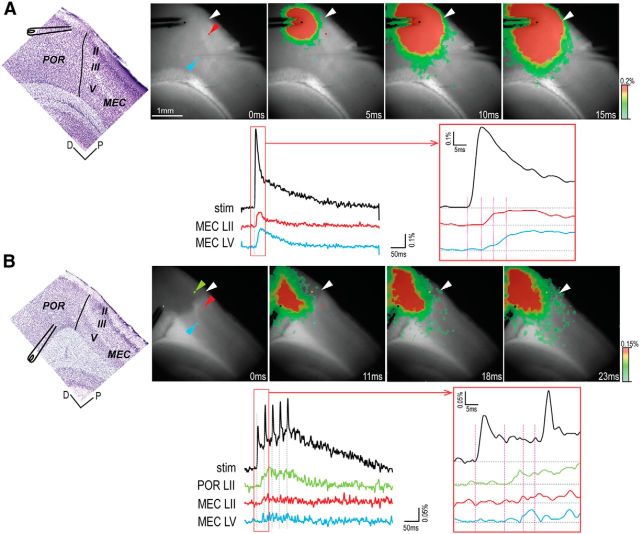
Figure 4.
Propagation pattern to MEC of activity evoked in POR. A, Direct propagation from ventral POR layer II to dorsal MEC. B, Propagation via POR layer II from dorsal POR layer V. Top, Left to right, Position of the stimulating electrode in a Nissl-stained thin section cut from the fixed slice after the recording experiment, and series of four selected images (time indicated below each image). Bottom, Optical signal traces from the stimulation site and the recording sites. The signal at the site of stimulation is indicated in black. Each recording site is indicated with a colored pixel (corresponding colored arrowheads; top), and the obtained signals are color-coded correspondingly. Right, Boxed area from the left panel with a higher time resolution. Vertical lines indicate the time of the images shown in the top. White arrowhead indicates the border between POR and MEC. D, Dorsal; P, posterior.

