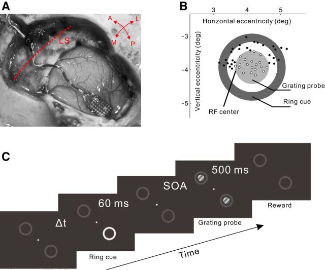
Figure 1.
Experimental design. A, Implantation of a microelectrode array in V1. LS, Lunate sulcus; A/P, anterior/posterior; M/L, medial/lateral. B, Illustration of the RF centers (indicated by small circles) of the neurons simultaneously recorded by the array of electrodes, and the layout of the ring cue and grating probe in the visual field. The concentric ring cue and grating probe were centered on an arbitrarily chosen RF, which was near the array center and could be different in different recording sessions. Only those recording sites (small empty circles) whose RF centers were located on the grating probe were used for data analysis. C, The temporal sequence of stimuli in a trial in the fixation task.

