Figure 4.

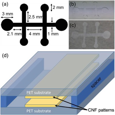
a) Design of microfluidic channels. Photos of b) PDMS mask and c) deposited CNF pattern on PET. d) Simplified schematic view of the microfluidic channel which is formed between CNF patterns in the assembled device.

a) Design of microfluidic channels. Photos of b) PDMS mask and c) deposited CNF pattern on PET. d) Simplified schematic view of the microfluidic channel which is formed between CNF patterns in the assembled device.