
Figure 8.
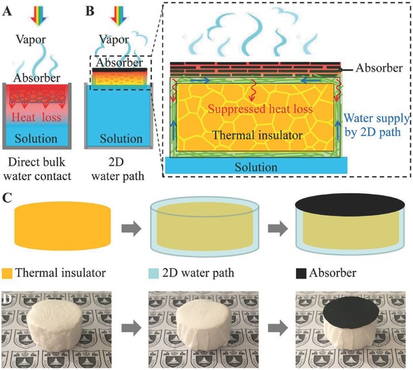
Schematics and the process flow. a) Schematics of a conventional solar steam generation with direct water contact. b) Schematics of solar desalination devices with suppressed heat loss and 2D water supply. c) Flow chart for the fabrication of solar desalination devices: polystyrene foam, cellulose coating, and GO film on the top surface. d) (Left) The physical map of polystyrene foam (thermal insulator), (Middle) cellulose (2D water path) wrapped over the surface of polystyrene foam, and (Right) GO film (absorber) on the top surface. Reproduced with permission.25 Copyright 2016, National Academy of Sciences.