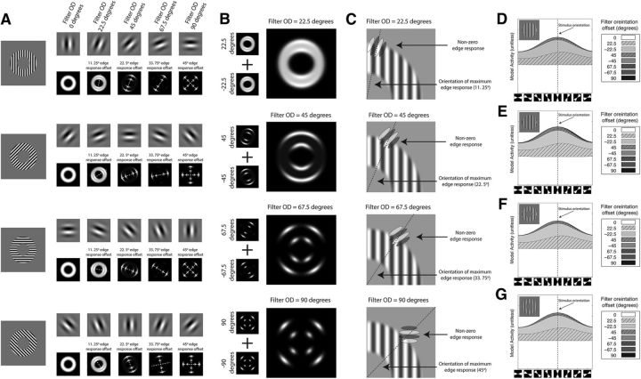
Figure 6.
Orientation coding and edge activity. A, The response to oriented gratings by filters with different levels of OD. Shown are four oriented grating exemplars with 0°, 45°, 90°, and 135° orientations. To the right of the exemplars is the response of filters with varying levels of OD. The orientation disparity of the filters increases left to right with 0°, 22.5°, 45°, 67.5°, and 90° offsets (top row). Below each filter the filter's pattern response. The dashed line placed over the pattern response indicates the orientation of the peak response to the edge. B, Summed response of the positive (clockwise) and negative (counterclockwise) OD filter responses a vertical grating pattern. C, Graphical depiction of interaction between filter disparity and the stimulus edge. Shown is the upper right quadrant of a vertically sine-wave stimulus. Semitransparent filters with varying OD are superimposed over the stimulus in the location corresponding to the peak edge response (indicated by the dashed line) for the filter. From the top to the bottom, plots show filters with increasing OD. D–G, Individual filters with varying OD contributions to the outer edge response. Shown are area plots showing the cumulative response of the filters to the outer edge response to a vertical grating. Inset, The grating exemplar from each stimulus set. The x-axis is a double wedge with a width of 45° region constrained to the outer edge that shifts stepwise in 22.5° steps (diagrammatically shown below the axis). The y-axis is the filter's response within the wedge. The filled regions are the response of individual filters. Filter orientation is described relative to the stimulus orientation. D, Sine-wave grating with a small inner radius edge. E, Square-wave grating with a small inner radius edge. F, Sine-wave grating with a large inner radius edge. G, Sine-wave grating with a small inner radius edge and heavy blur function.

