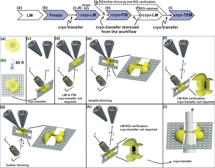
Figure 1. Schematic presentation of the workflow.
(a) Live cell imaging. (b) Plunge or high-pressure freezing of the sample for cryo-preservation (note, cells can be either cultured on the grid in (a) or in case of suspension be added onto the grid at this stage). (c) Cryo-light fluorescence microscopy in the PIE-scope to identify regions of interest. (d) Simple lateral translation of the sample brings the selected region of interest under the FIB/SEM columns. (e) Once the region of interest is under the FIB, a lamella can be thinned down. The angle between the prepared lamella to the grid plane can be controlled by the stage tilt. (f) Simple translation and tilt of the prepared lamella inside the system allow verification of successful targeting of the region of interest with light microscopy. (g,h) An optional repeat of (e) and (f) for further thinning of the lamella. Since two cryo-transfers are required, the system allows rapid and multiple intermediate verifications of targeting with optical and scanning electron microscopes. The x,y,z-axes shown in c-h correspond to the stage axes of the FIB/SEM. (i) Once the region of interest is successfully targeted and optically verified, the lamella is cryo-transferred into a TEM for high-resolution sample analysis. Distances and dimensions throughout the figure have been adapted for illustrative purposes and are not representative.

