Fig. 2.
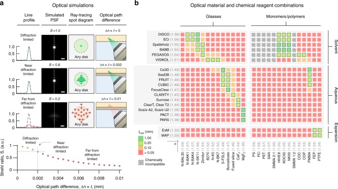
Holder design for OTLS imaging. a Optical simulations of the system’s point spread function (PSF) and Strehl ratio (S), and ray-tracing spot diagrams, are shown for scenarios in which the optical path difference (Δn × t) is negligible, small, or large, which results in diffraction-limited (S ~ 1.0), near-diffraction-limited (S > 0.8), or aberrated (S < 0.8) imaging performance, respectively (scale bars: 1 μm). The dependence of the Strehl Ratio, S, as a function of Δn × t is plotted, indicating that for diffraction-limited imaging, the condition that Δn × t < 0.002 mm should be maintained. Based on this condition, potential glass and monomer/polymer holder materials are shown in (b). The color scale indicates the maximum material thickness, tmax, that is allowed based upon the intrinsic mismatch, Δn, of those materials with published clearing protocols. Chemically incompatible combinations of materials and chemical reagents are also indicated

