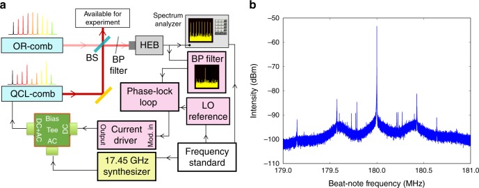
Fig. 1.
Experimental set-up. a Schematics of the experimental setup employed for full stabilization, control and characterization of the QCL-comb. The beams of the OR-comb and QCL-comb are superimposed by means of a beam splitter (BS) and then mixed on a fast detector (HEB: hot-electron bolometer). The HEB signal is acquired on a spectrum analyzer (Tektronics RSA5106A) while the two stabilization loops act on the QCL bias. The yellow background object represents the RF synthesizer used for injection locking, while the pink background objects are related to offset stabilization through phase-lock loop (BP filter: band-pass filter, LO reference: local oscillator reference). All the oscillators and the spectrum analyzer are frequency-referenced to the primary frequency standard. b Phase-locked beat-note signal acquired with a 2 MHz span and 10 Hz RBW. The two sidebands indicate a phase-lock electronic bandwidth of 400 kHz

