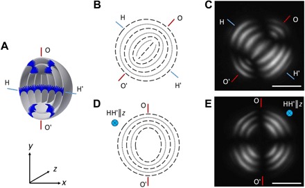
Fig. 1. NP-free Ch-CNC droplets.

3D (A) and cross-sectional schematics (B and D) and corresponding POM images (C and E) of the Ch-CNC droplets, with the OO′ and HH′ axes perpendicular to the z axis (B and C) and the HH′ axis parallel to the z axis (D and E). The light gray rings and dark blue rods in (A) represent the Ch-CNC pseudolayers and the CNCs, respectively. The dashed and dotted lines in (B) and (D) represent the CNC pseudolayers. In (C) and (E), φ0 = 4.3 × 10⁻². Scale bars, 10 μm.
