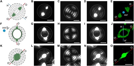
Fig. 2. Self-assembly of NPs in the Ch-CNC droplets.

Schematics of the composite latex NP/Ch-CNC droplets with BP (A), TR (F), and core-shell disclination (CSD) (K) assemblies of the NPs. Representative fluorescence microscopy (B, G, and L), POM (C, H, and M), and merged (D, I, and N) images of the same NP/Ch-CNC droplet. (E, J, and O) 3D confocal fluorescence microscopy images of the NP assemblies with BP (E), TR (J), and CSD (O) structure. φNP is 5.5 × 10⁻⁴ in (B) to (E) and 1.1 × 10⁻³ in (G) to (O). φ0 = 4.3 × 10⁻². Ch pseudolayers form flat-ellipsoidal structures in (A) to (J). Scale bars, 10 μm. Left: Orientation of the OO′ and HH′ axes (as in Fig. 1) and the corresponding notations for the orientation of the OO′ and HH′ axes with respect to the z axis (the optical axis of the microscope). The dashed and dotted lines and green deposits represent the CNC pseudolayers and latex NPs, respectively.
