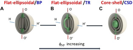
Fig. 4. Morphogenesis in the Ch-CNC host droplets and NP assemblies.

(A) Flat-ellipsoidal/BP. (B) Flat-ellipsoidal/TR. (C) Core-shell/CSD. Gray planes represent the Ch-CNC pseudolayers. Green color marks latex NP assemblies. Labels above each schematic show the corresponding Ch-CNC packing mode (red font) and the NP assembly mode (blue font). To illustrate NP assembly, the schematics does not show the continuous twist of the CNCs.
