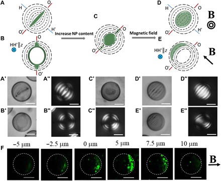
Fig. 5. Interactive morphogenesis in Ch-CNC droplets laden with magnetic NPs.

Representative schematic (A to C) and corresponding bright-field (A′, B′, and C′) and POM (A″, B″, and C″) images of the Ch-CNC droplets loaded with Fe3O4 NPs with TR (A′, A″ and B′, B″) and CSD (C′ and C″) assemblies. φNP = 9.7 × 10⁻⁴ and 1.9 × 10⁻³ in (A′ to B″) and in (C′) and (C″), respectively. No magnetic field is applied. Representative schematic (D and E) and corresponding bright-field (D′ and E′) and POM (D″ and E″) images of the Ch-CNC droplets loaded with Fe3O4 NPs at φNP = 9.7 × 10⁻⁴ and exposed to a 0.35-T magnet for 3 days. φ0 = 4.3 × 10⁻² in all the samples. Scale bars, 10 μm. Top row shows the orientation of the OO′ and HH′ axes (as in Fig. 1) and the corresponding notations for the orientation of the OO′ and HH′ axes with respect to the z axis (the optical axis of the microscope). Dashed lines and dotted lines and green deposits represent the CNC pseudolayers and NPs, respectively. (F) Z-stack fluorescence microscopy images of the Ch-CNC droplets shown in (D) and (E). The 0-μm position corresponds to the central plane of the droplets, and the images were taken on the top (negative values) to the bottom (positive values) of this plane. φNP = 9.7 × 10⁻⁴ and φ0 = 4.3 × 10⁻² in all the samples. Scale bars, 10 μm.
