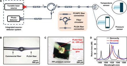
Fig. 3. Bioresorbable interfaces to the optical sensors.

(A) Schematic illustration of the setup used for spectral analysis of bioresorbable FPI sensors. FC, ferrule connector; APC, angled physical contact. (B) Photograph of a PLGA fiber [diameter (d), ~200 μm] formed at the tip of a commercial SMF. (C) Photograph of a PLGA fiber aligned and fixed to the bottom diaphragm of a bioresorbable FPI pressure sensor. The bioresorbable glue holds the parts together. (D) FP resonance signals collected at different stages of the process of integrating the fiber with the surface of the sensor. The steps involve aligning the fiber tip to a non–air cavity region of the device (noncavity; black) at a perpendicular incidence and minimizing the distance between the tip and the device, laterally repositioning the fiber to align the tip close to the center region of the diaphragm, applying and curing the bioresorbable glue (on-cavity and glued; red), releasing the device from the water-soluble crystal bond by heating the carrier wafer (released; blue), and removing the residual crystal bond by dipping in warm water.
