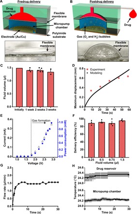
Fig. 2. Fluidic and electrical characteristics of the wireless optofluidic system.

(A and B) Top: Schematic diagram of the electrochemical micropump. Applying current to a pair of electrodes initiates pumping through expansion induced by electrochemical phase change of liquid water into hydrogen and oxygen gases. The resulting pressure in the micropump chamber deforms the flexible membrane and delivers the drug. Bottom: Images of mechanical deformation of the flexible membrane induced by water electrolysis. Scale bar, 0.3 mm. (C) Fluid volume in the drug reservoir as a function of time. (D) Comparison between experiment and modeling of maximum displacement of flexible membrane induced by water electrolysis. (E) Current-voltage-power characteristics of the electrochemical micropump. (F) Total infusion efficiency from various loaded volumes in representative devices (n = 3 devices). (G) Flow rate in a microfluidic channel as a function of time. (H) Temperature of the drug chamber (top) and micropump chamber (bottom) during the electrochemical pumping process (3 V). All data are represented as means ± SEM.
