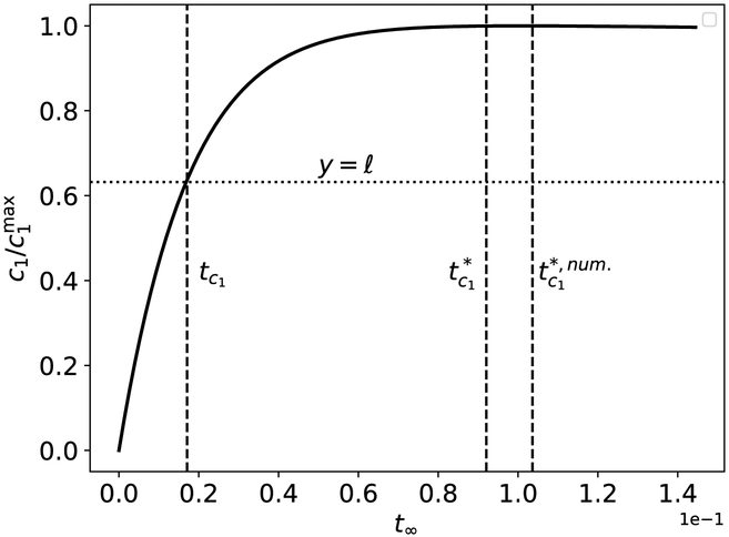
Figure 5: The validity of and a graphical representation of its comparison with tc1 for the Michaelis–Menten reaction mechanism (12).
The solid black curve is the numerically-computed solution to (13a)–(13b). The left-most dashed vertical curve is corresponds to tc1, and the middle dashed vertical curve corresponds to the estimated value . The dashed vertical line corresponds to the numerically-computed , which is labeled as in the figure. Notice that provides a much better estimate of the time it takes c1 to reach its maximum than tc1. The initial concentrations and rate constants used in the numerical simulation are: k1 = 0.1, k2 = 10, k−1 = 1, and (units have been omitted). Time has been mapped to the t∞ scale: t∞(t) = 1 – 1/ ln[t+exp(1)]. Note that the mass action equations have only been integrated from t = 0 to for clarity.

