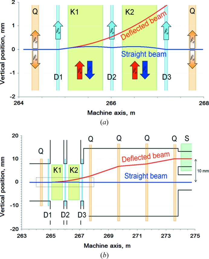
Figure 3.
Vertical plane beam trajectories between kicker and septum (a) and the same but magnified in the kicker region (b). Coloured rectangles represent the field regions of different magnetic components: quadrupoles (Q), kickers (K), dipoles (D) and septum (S). Arrows show the direction of magnetic deflection.

