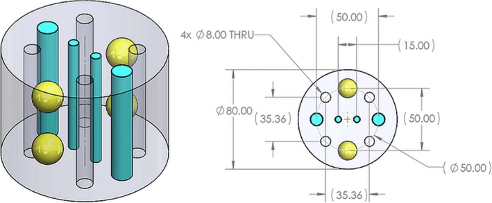
Figure 5.

Isometric (left) and planar (right) views of the calibration phantom. On the planar view, the label Ø indicates diameter and THRU indicates through holes. There are four (4 × ) through holes in the phantom which are filled with water upon placement of the phantom in water. All dimensions are in millimeters.
