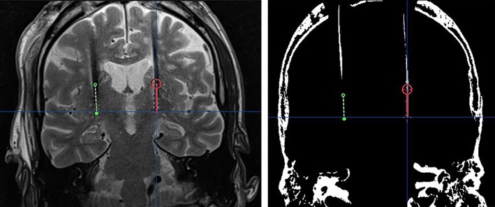
Figure 2.

Lead visualization and plotted lead trajectory on MRI (left) and iCT (after windowing; right) in the same patient using the probe view in iPlan. The red and green lines represent the left‐sided and the right‐sided lead‐artifact, respectively. [Color figure can be viewed at wileyonlinelibrary.com]
