
Figure 3.
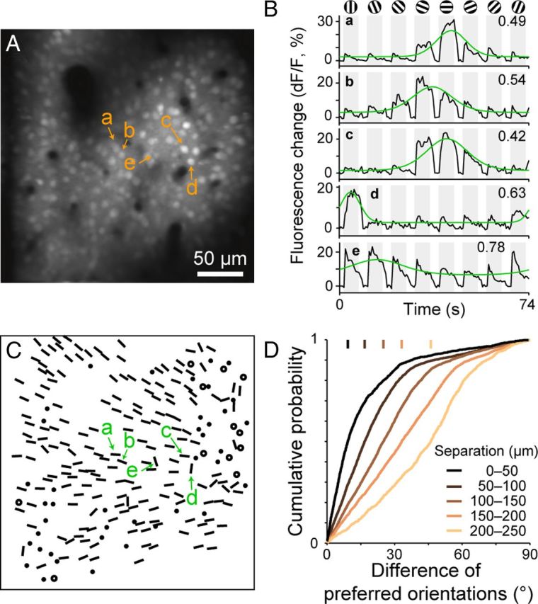
Orientation preference map obtained by two-photon calcium imaging. A, A recording region loaded with OGB-1. The image was taken in layer 2 in a tangential plane 145 μm below the cortical surface. B, Time courses of fluorescence changes (dF/F) of five selected neurons (a–e in A). Responses were averaged across 60 stimulus presentations. Gray shading indicates periods of stimulus presentation. Fitted orientation tuning curves are superimposed in green. The values in the upper right corners are CVs of the tuning. C, Orientation preference map based on single-neuron responses. Oriented bars: preferred orientations of orientation-selective neurons with well fitted orientation tuning curves (R2 ≥ 0.7). Filled circles: orientation-selective cells with poorly fitted tuning curves (R2 < 0.7). Open circles: visually responsive, orientation nonselective cells. D, Relationship between the difference in the preferred orientations of two neurons and the physical distance between them in the cortex. Vertical bars: the median values of differences of preferred orientation for five groups of neuron pairs with different physical separations.